

DIY Senville Mini Split AC Installation – Air Conditioning Install without Professional Help
In this article, I am going to show you how I personally installed a mini split ac in my garage: the whole process…just me. I am going to discuss:
- Why I chose a DIY HVAC route
- Selecting a minisplit air conditioning system or heat pump, sizing and performance
- Pre-installation preparation
- Installation details
- Avoiding mistakes and correcting them if necessary
- Cost details
- Performance observations
Disclosure: I have included links to the products I used below. Many are affiliate links. If you use them and make a purchase I make money. Senville Air Conditioners and EPATest.com sponsored the video I published on YouTube, although I selected and used both products before I reached out to the companies as potential sponsors.
Why DIY
First and foremost I will review why I chose to go the DIY route and limitations on why you may not want to do-it-yourself. If you are here, you obviously have a room that is uncomfortably hot or cold. My uncomfortable room was my garage workshop which reached afternoon temperatures of 95F or 35C when outside temperatures were only 86F or 30C. A friend had a comparable system installed for $5000; my DIY install set me back around $2000 including equipment, tools, permits, and certification.
Pros
I chose to go the DIY route for four main reasons ordered by importance.
- Intrinsic benefit – Exercise your inner maker
- Opportunity to learn – I feel very comfortable with do-it-yourself electrical, plumbing, and framing, but air conditioning systems are surrounded by near superhuman lore.
- Cost effective – relative to the expense and hassle of arranging a contractor to perform the work.
- Legal – DIY HVAC install is legal in my jurisdiction for my application.
Cons
Just because I chose the DIY doesn’t mean everyone should. Hopefully discussing the limitations of a DIY approach will help you decide if this route is for you.
First, do it yourself HVAC install may not be permitted in your jurisdiction for your application. In my county, a homeowner can perform any work they want on their home if they live there for one year afterward and pull the appropriate permits. Will your DIY installation be legal in your application in your jurisdiction?
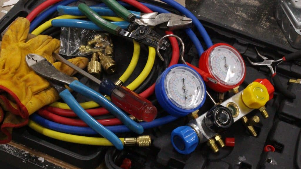
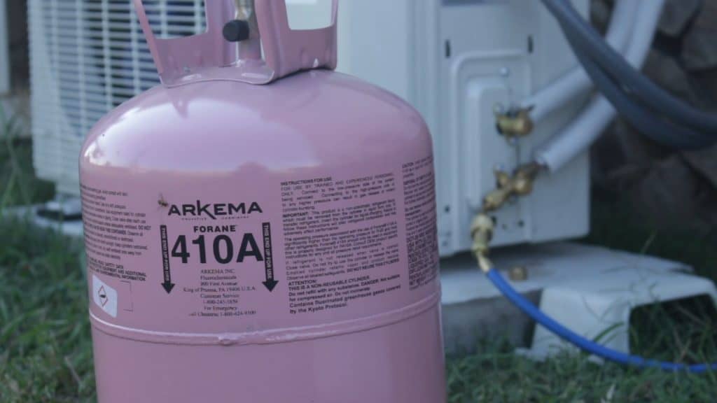
A quick search online for DIY HVAC advice will lead you to no shortage of cautionary tales and even “pro-only” walls shielding you from information that will help you work more safely. The concepts involved with HVAC are straightforward, but there are a lot of moving pieces. This was the most advanced DIY project I have ever undertaken. In addition to working with pressurized refrigerant, you will need to provide for the electrical supply typically 240VAC. There is also no shortage of folks dissuading you from installing a 240V circuit in your own home for fear of the actual hazards and purported consequences such as claims denied by homeowners insurance companies. I understood the hazards and coverage of my homeowners policy before I decided to proceed. I hope you find this content informative and encouraging for prospective DIYers, but you have to assess your skill set and decide for yourself whether you can do it safely and correctly. Do you doubt your skillset or your knowledge? Safety Note: if your systems uses R410a refrigerant be sure your equipment is rated for the higher working pressures. I include the exact tools I used in the section below.
Refrigerants generally have a bad or very bad impact on the environment. Venting isn’t cool. Don’t be uncool. In the US, EPA Section 608 type II certification is mandatory for technicians including homeowners maintaining, servicing, or repairing mini split ac systems using R410a. I obtained my certification exclusively for this project. It took me about a week to study and pass the test–I am not a mechanical engineer but I found my undergrad thermodynamics course very helpful. Are you trained to responsibly handle refrigerants?
When I purchased my mini split, I had to consider the distinct possibility that the warranty may not be honored because I installed it myself. There are systems such as Mr Cool that are marketed for DIY application, but based on Jeremy Hoffpauir’s experience–where he was required to hire a HVAC professional to validate a warranty claim–warranty support for DIY installation is distinctly in the “maybe” category. I justified proceeding without assurance of warranty support for several reasons.
I created a checklist to facilitate meticulous picture taking and measurement recording. I also did a lot of research to ensure my own understanding of the system would permit me to work directly with the manufacturer to troubleshoot any issues. By carefully documenting my installation steps and supplementing with photos and measurements, and providing my checklist with all those records to the manufacturer, I may be able to mitigate the their DIY concerns if there is a bonafide warranty issue. Further, I thought my EPA Section 608 Universal Certification may be sufficient professional qualifications for warranty purposes. After all, I could legally troubleshoot and repair (though not install in my state) someone else system and send them an invoice for those services. Do your concerns about manufacturer’s warranty coverage outweigh the benefits of a DIY install?
If you answer no to any of these questions, I would recommend you not proceed with a DIY installation. Instead, I recommend you pursue action that permits you to answer yes to these questions.
Sizing
After I decided the DIY approach was for me, I had to figure out what size system I needed. Before deciding to install a mini split ac, I made several attempts to assuage the afternoon summer heat in my garage. Heat is energy; this means my garage was accumulating too much energy. Where was the heat coming from? First, I insulated the west facing garage door which was obviously hot to the touch late in the day but not after I insulated it. I used 1.5” of expanded polystyrene, but it was still hot in the afternoon. After insulating the garage door, I used an IR thermometer to look for other heat sources. The source was then obvious: the uninsulated ceiling. I measured June temperatures of nearly 150F in my attic above the garage. I opted to install a healthy ~12.5” or ~32cm of cellulose insulation. This was a big win bringing the afternoon temps from 95F or 35C down to nearly the outside peak temperatures of 86F or 30C. This was still too hot to work comfortably. I would need to pump the heat outside of my garage.
With no windows in which to install a window air conditioner, a minisplit air conditioner was the obvious choice. Furthermore, I could install a mini split with heat pump capability to pump energy from outside to inside during the winters. But how big a unit do I need?
I used this calculator because it includes a garage only option but I also compare the results with other calculators and rules of thumb. I played around with the options in several different scenarios and could see that the garage ceiling insulation made the biggest impact on cooling load.

I used an outdoor design temperature of 91F and arrived at a cooling load of 6,100 BTU/hr (including a moisture removal allowance) to maintain 75F. With an outdoor design temperature of 22F i would require a heating load of 8,400BT/hr to maintain 55F. This was a bit surprising to me because I assumed my application was cooling limited. A 9,000 BTU/hr unit should cover my application.
During the summer the excess cooling capacity allows me to move wasted energy (heat)–from electrical devices like lights and tools–outside. In the winter, the wasted energy is useful to help heat the space and get it potentially higher than my indoor design temperature of 55F. I estimated my electrical load to be ~1.5hp * 75 % duty cycle = 3.8kBTU/hr * 0.75 = 2.9kBTU/hr.
Features
I mentioned earlier that heat pump capability was a requirement for me since I plan to use the garage workshop year round. Another important feature to me is efficiency. Saving money is nice side effect of efficient mini split ac, but I am more concerned with minimizing the energy I use. Using less electrical energy results in less carbon dioxide emissions. Where is the right trade-off between efficiency versus cost? Many will want to do a return on investment calculation to see what the payback period is on a more efficient unit. Since my primary concern is long-term energy reduction I wanted to get one of the the highest efficiency units. I decided somewhere as close to 25 SEER is where I wanted to be.
To get such a high energy efficiency rating, it is necessary to use inverter technology. Basically this type of system runs continuously varying the systems output based on load. A conventional system switches on, runs at 100% for a while, then sits idle until called upon again. By running at something less than 100%, an inverter based system avoids wasting energy to bring the system back up to 100% capacity repeatedly.

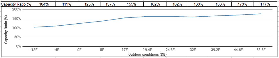
Another item of which to be aware is the range of temperatures in which the unit will be expected to operate. Air conditioners lose efficiency as the outdoor temperature increases. Heat pumps lose efficiency as the temperature decreases. Every unit will have different performance characteristics across their operating range. You may have to reach out to a manufacturer directly for this information; I did. How hot or cold will it get outside? Be sure to select a unit that will be capable of delivering your heating and cooling load performances in the conditions you will encounter.
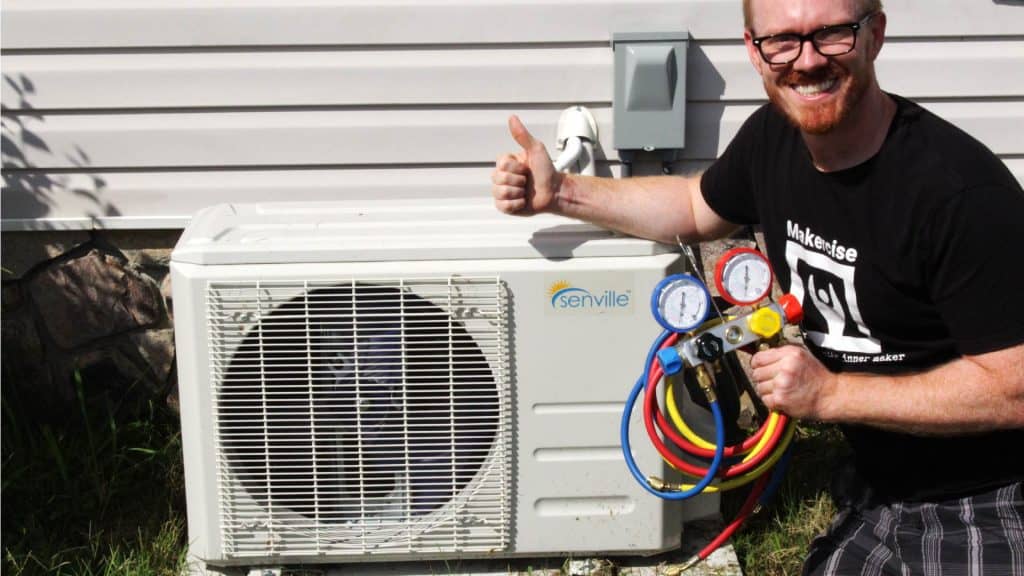
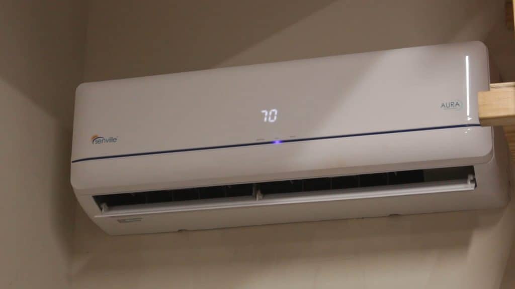
Selection
There are a number of manufacturers that make systems that meet my criteria of 9,000BTU/hr heating and cooling capacity and >23 SEER. To help me select among the alternatives, I read through manufacturer documentation, perused Amazon reviews, considered unit price, and factored shipping costs. Ultimately, I decided on the Senville Aura 9,000BTU/hr mini split ac with the piping kit. I ordered it and received it about 1 week later. The unit came on a pallet in 3 boxes, indoor unit, outdoor unit, and hoses. The outdoor unit is heavy but two people can manage it. Note: if you have Fedex Freight deliver to a residential address they may try to charge you $125 for a lift gate. In my case, they did not tell me this before hand. I spent 20 minutes on the phone with them before they dropped the charge. Not cool Fedex.
Pre-Installation Leg Work
In my jurisdiction, a permit for a mini split ac installation including electrical work cost me $50 USD. In addition, as of January 2018 the EPA requires technicians who perform work that may release R410a to be certified. I found a HVAC supply store about 45 minutes away that proctors the EPA Section 608 Universal Certification exam developed by EPATest.com. It cost me $105 USD. I drove up and got the study packet, studied for 1 week, and returned to take the exam. I passed. With certification and permit in hand, my installation was 100% legit.
Installation
Follow the instructions
Regardless of what unit you choose, follow your manufacturer’s installation instructions. I am writing this article to be generally instructive but this article isn’t a substitute for following the instructions that came with your unit. You should have a checklist and document each step, take pictures, and record measurements especially if you deviate from the instructions. I deviated from the instructions in some places, for instance side clearances on indoor unit that were infeasible where I installed the unit. I also pressure testing the system with nitrogen even though the manufacturer only specified a vacuum test. Ensure all test equipment you use is rated for the refrigerant in your system. For me, R410a meant I needed equipment rated to 800PSI working pressure.
Placement
Before you can start installing the unit, you will need to coordinate where you are going to place the indoor unit and outdoor unit. Mounting the indoor unit in a central location in the room is better for even heating and cooling. If the interior and exterior unit are farther apart you will need longer hoses, and be aware that there is a limit to how far apart they can be. Routing of the high and low pressure lines, the electrical cable, and the drain line are all considerations to factor into placement of the unit.
I chose a location on the exterior wall of my garage. I wanted to get the unit about 8’ up on the wall, and because of my overhead garage shelving I chose the corner right above my electrical box. The exterior unit could then go right inside the fence in the backyard. All with only a 16’ hose kit. I chose to route the lines and cable behind the sheetrock, along the inside of the garage in a raceway, then through the wall at the outside unit. I avoided installing a vinyl conduit for the hoses to dress up the exterior of my house and also provided a raceway for the electrical cable from the panelboard to the outside disconnect.
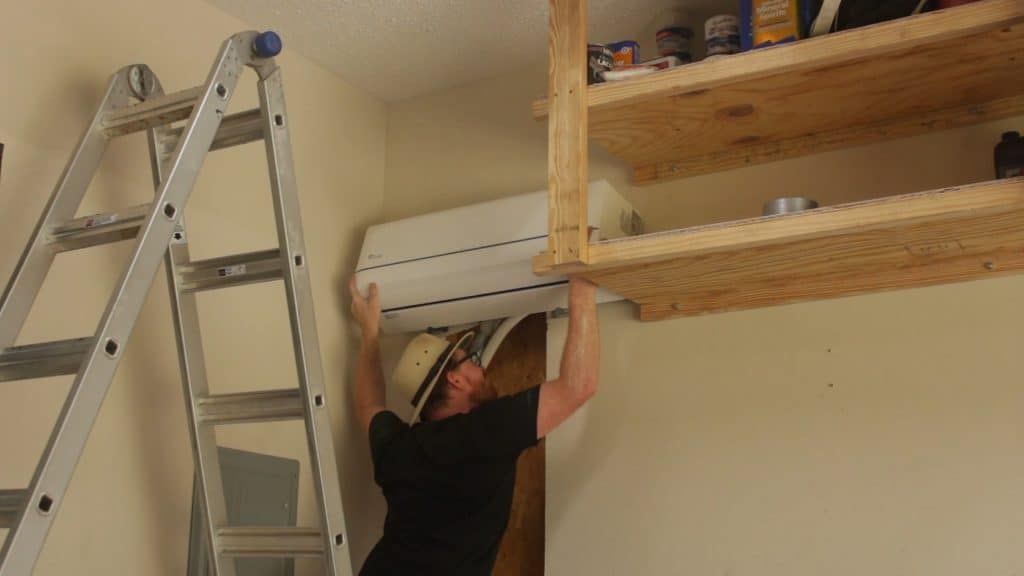
Indoor Unit
Your unit should come with dimensions or a template for placing the bracket that will hold the indoor unit. The dimensions in the instructions for my unit were not super clear so I directly measured the indoor unit to determine dimensions for mounting the bracket. Be sure the bracket is level. Drill an angled hole through the wall if you are directly exiting the building.
Wire the indoor-to-outdoor cable to the indoor unit by landing the wires on the correct terminal blocks. Use moderate force to tug on them to ensure the individual conductors are well seated. Take a picture of where you land the wires.
Bend the tubing to the correct direction for your application being careful to make gradual bends. Do not kink the lineset. Although I did not use a bender, you can use a tubing bender to ensure you do not kink the lineset. Take a picture of the lineset to show how you bent to a gradual radius. The insulation will likely obscure the most critical areas. I did not disturb the insulation to confirm my hose was not kinked close to the unit, but I felt confident it wasn’t by maintaining a gradual bend and feeling through the insulation for any obvious signs of a kink.
Seat the drain line hose as indicated in the installation instructions provided by your manufacturer. Use tape to wrap the lineset, electrical cord, and drain line together. This will be helpful regardless of whether you exit the building immediately behind the unit or route the bundle through the building somewhere first. Leave at least 6” or 150cm unwrapped to provide room to connect the lineset to the flare fittings.
Hang the unit on the bracket and ensure it is completely seated.
Outdoor Unit
Finalize the location of your outdoor unit and ensure that you budget some slack in your copper lines. Unless you plan to cut and flare your lines, I’d recommend leaving several feet of line. You can hide the surplus line by coiling or looping it behind the unit on the outside or in a raceway on the inside. The only way to get it exact is to cut and flare the line. I recommend the kit with factory flared lines.
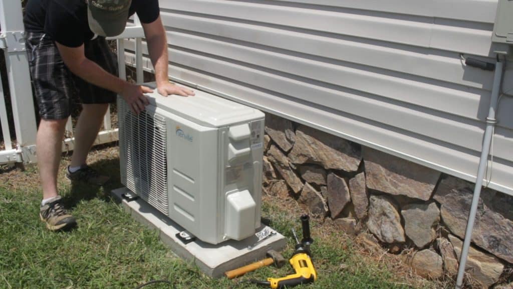
Prepare a mounting location. I used two 80lbs. bags of concrete but you can also buy purpose built AC mounting pads made from pre-cast concrete or plastic. Mount your unit securely to the pad. I used ⅜” concrete anchors.
Copper Tubing Lineset
Route the copper lineset between the outdoor and indoor units. Be careful not to bend the tubing too sharply. It can kink, and if it does the wall will be weakened even if you try to get the kink out. Copper tubing benders are available to avoid kinking copper tubes.
I initially planned to run my tubing through a hole behind the indoor unit and out a hole in the sheetrock at the bottom of the stud cavity. This was infeasible; I ended up cutting the sheetrock from the indoor unit down to the bottom to expose the entire stud cavity. Running the tubing through an exterior wall is by far the easiest way to get the tubing out of the house. Decide which of the following is preferable to you: interior sheetrock work, interior line and cable raceway, or exterior line and cable raceway. One of these will be required.
Making Lineset Connections
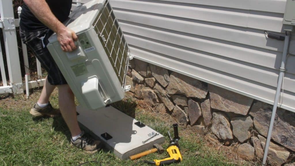
The connections are the most critical part of the installation since leaking refrigerant is the biggest risk installation problem. Both the indoor and outdoor unit should be under pressure when you receive them. The outdoor unit contains refrigerant inside with valves, so you can access the flare fittings without releasing pressure. The indoor unit is pressurized with nitrogen from the factory so you know it is not leaking. You cannot access the flare fittings to connect the lineset until the caps are removed. Loosen until nitrogen can be heard leaking and wait for the pressure to bleed down–note in the video I did not do this long enough and the end cap shot off and across the garage…safety glasses for the win. If you find the indoor unit is not under pressure from the factory, contact the manufacturer to ensure this does not indicate a factory defect.
The highest likelihood for a problem is leaks around the lineset fares. Be sure the hose is aligned so the flare mates well and the nut tightens easily. Wiggle the hose so the nut can seat fully under hand tightness. Your installation instructions will likely specify a torque for tightening the flare nut. Use a crows foot socket and a torque wrench and tighten to the manufacturer specification. If you turn the crows foot 90 degrees to the torque wrench you do not need to convert the torque setting to account for a longer moment arm.
The instructions that came with my Senville Aura indicated a vacuum test is sufficient to guarantee the integrity of the system. I used a 150cf cylinder of dry nitrogen (nothing special about “dry” just not liquid) to pressurize the system to 250 psi. This is around the pressure of saturated R410a in a sealed container at 84F or 29C. I left the system for 12 hours to see if the pressure changes.
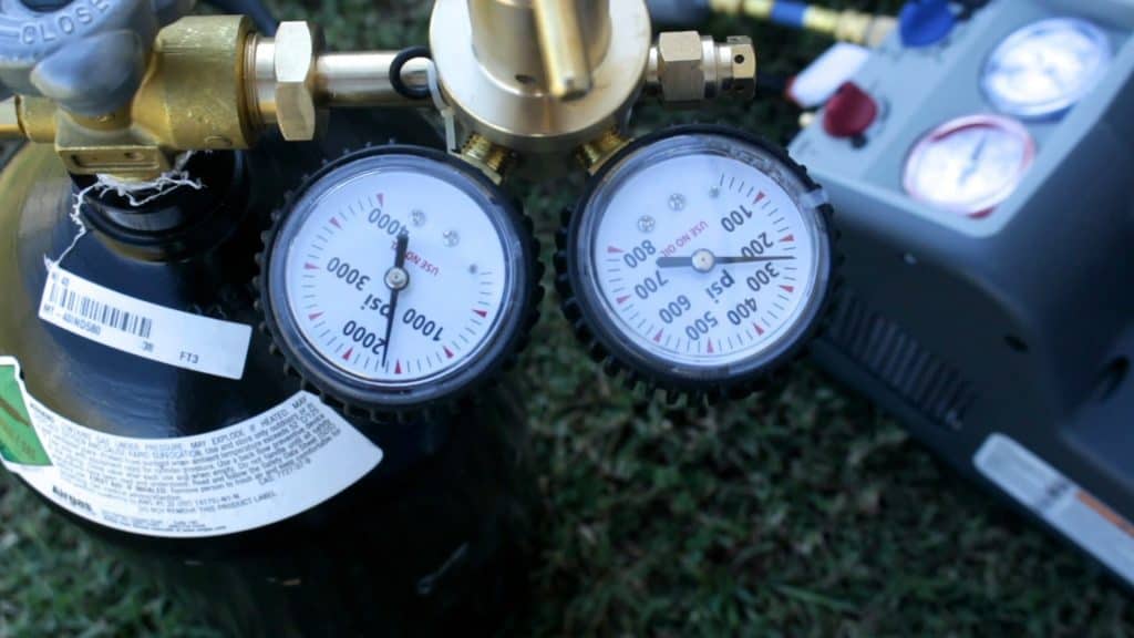
I connected a regulated nitrogen tank, vacuum pump, and micron gauge to the system through a manifold gauge set. I used the black port for the vacuum pump, the yellow port for the micron gauge, and the red high/pressure line for the nitrogen. I watched the red gauge while I adjusted the nitrogen regulator to a specific pressure. The regulator has a gauge but it wasn’t very accurate under 100psi.
I connected my manifold gauge set to the system using the blue line. I used a low-loss fitting (Yellow Jacket part 19109) although the manufacturer doesn’t recommend using it with R410a. The low loss fitting really cuts down on the amount of refrigerant lost when disconnecting hoses. Hose-end ball valves are an alternative method for minimizing refrigerant loss.
I connected the low loss fitting to a 5/16” to ¼” mini split ac adaptor (Yellow Jacket part 19173). I don’t recommend that part either, but in this case it is because I think there is a better tool to minimize refrigerant loss during disconnection. If I end up doing another install in the future, I would try the CD5060 which features an integrated thumb operated Schrader valve depressor. The mini split only has a low side port, and this is where the adapter screws on. The high pressure side of the mini split system has no provision for connecting a hose.
Some fluctuation is expected since the temperature will vary over 12 hours. You can use a pressure calculator to determine how the pressure may change. For instance, a nitrogen pressure of 250psi at 91F would only be 239psi if the temperature dropped to 70F with no leaks. If the temperature goes up you may see a pressure increase. If you can keep them out of the weather, leave your gauges connected so you don’t lose any pressure disconnecting and reconnecting them. Leaving the gauges for a longer duration may give you even more confidence that your system–primarily your flare fitting connections–are not leaking. Take pictures of or record in your checklist the temperature and pressure readings at times separated by at least 12 hours.
Wire the Unit
Most of the units I looked at are 240VAC appliances. Only work with de-energized conductors and equipment. Ensure your installation meets current National Electric Code requirements and any more restrictive local codes.
While my lineset was “soaking” under pressure, I worked on the electrical connections.
I installed a disconnect near the outside unit, and pulled a supply circuit to the disconnect from the panelboard. I left it unconnected at the panelboard. The purpose of the disconnect box is to allow isolation of the supply from the outdoor unit without having to access the panelboard. The indoor-to-outdoor cable does not need a disconnect in my opinion. You should talk to your inspector to see what your local authority having jurisdiction (AHJ) wants to see.
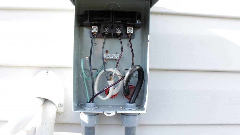
I sized the supply circuit to safely deliver the rated current to the mini split ac. Mine was rated to draw a minute 3A and recommended a maximum 15A fuse. I pulled 14AWG romex and used a 15A two pole breaker. I routed the indoor-to-outdoor cable from the indoor unit to the supply disconnect. On both ends I used a marker to color the white insulation black thus denoting it as a hot leg. I landed the two hots and ground from supply line at the disconnect. From there I used THWN, two black and one green conductor to do from the disconnect to the outdoor unit. Using THWN or another insulation rated for wet locations is important even though I ran them through liquid tight conduit. A installed a second liquid tight conduit to bring the indoor-to-outdoor cable to the outdoor unit from the disconnect box. I used spade lugs on the THWN to provide a solid connection of the stranded wire to the terminal block in the outdoor unit. The indoor-to-outdoor cable was provided with spade lugs from the factory.
You should wait to install the double pole breaker in your panelboard until the very last thing. De-energize the panel by opening the main breaker. If de-energizing the panel is not feasible, wear appropriate personal protective equipment and do not contact bus bars. Gloves, long sleeve fire resistant shirt, a face shield, safety glasses, and insulating tools will help you work safely. Again, save this for last after everything else is connected. Land the ground wire in the panel then land the two insulated conductors on the two pole breaker. Ensure the breaker is in the off position. Leave it off until the system is charged. Carefully seat the breaker into the box, extra carefully if your panelboard bus bars are energized.
Charge the System
In the article I linked earlier, the HVAC professional hired by Jeremy Hoffpauir said the system had no refrigerant in it. His unit was cooling initially, so there was initially refrigerant. The conclusion was it had leaked out of the indoor unit due to a factory defect. This is the exception not the rule. The highest likelihood is a leak from the lineset connection points. Be sure you convince yourself that there are no leaks in your system prior to releasing the refrigerant from your outdoor unit into the lineset and indoor unit. You should log the measurements that you observe and record them in a checklist in case you ever need to convince the manufacturer that there were no leaks. In my opinion a pressurization test over a 12-24hr period, torque wrench setting picture, and vacuum levels are sufficient to document a quality installation.
After you are sure you are working with a sealed system that doesn’t leak under pressure, the next order of business is to get all the air and moisture out. Even small amounts of water vapor will wreak havoc on the compressor over time. Triple evacuation is the only way to ensure there is no moisture or non-condensible gases in the system. Basically this consists of evacuation, breaking the vacuum with nitrogen, venting nitrogen, and then repeating two additional times.
Before releasing refrigerant from the pre-charged outdoor unit, you need to evacuate the system to a low micron level. If you have pressurized the system with nitrogen, you need to vent the nitrogen first. Bleed the system down to a few psi on your manifold gauge. Turn on your two-stage vacuum pump and open the manifold gauge ports to the pump and the micron gauge to start pumping the system down.
The micron gauge is the only way to tell if you have a quality vacuum; don’t rely on your manifold set or timing how long you run the vacuum pump. Know that you have achieved a quality vacuum and document the micron level you achieve. Also, after a quality vacuum is obtained you should watch the vacuum level with the pump isolated and off to see if the vacuum level creeps up. You should expect the level to creep some before stabilizing. Unless you have vacuum rated hoses and manifold, you should expect some creep even after stabilization. A few hundred micron over 10 minutes is reasonable. Document your vacuum creep and stabilization levels. If your micron gauge doesn’t stabilize you should suspect a leak. But that won’t happen because you already pressure tested and that held for over 12 hours, didn’t you?
The best professionals use Schrader valve core removal tools and ½” or large diameter hoses to achieve vacuums well below 500 microns. With smaller ¼” diameter hoses especially ones that are not vacuum rated you will be unable to achieve these vacuum levels. I was satisfied with a vacuum level of 1300 microns considering my manifold gauge set and hoses were not vacuum rated and I was only using ¼” diameter hoses. If I did this frequently, I’d buy the core tool and large diameter hose.
Follow the manufacturer’s instructions for releasing refrigerant. Note: This is a point of no return. Once you let the refrigerant out of the outdoor unit, you cannot disconnect the lineset without first recovering all the refrigerant from the system–more on that later.
Put the outdoor electrical disconnect plug in. Then flip the new breaker on in your panelboard. Follow the manufacturer instructions to turn your system on.
Once the system starts cooling or heating, you will notice the pressure on the low side gauge drops. This is the normal dynamic pressure of the system during operation. It is also a good opportunity to disconnect your 5/16” to ¼” adapter from the system. Doing so with the system on will result in less refrigerant loss due to the lower pressure. Note I disconnected my low loss fitting from the adapter before disconnecting the adapter. When disconnecting the adapter do so quickly to minimize refrigerant loss.
Avoiding mistakes and correcting them if necessary
My mistake
I ran into an issue when installing my unit. The instructions I have written above are all steps I took in the order I wish I had taken them. Instead, I followed the manufacturer’s instructions–this was not the problem–to vacuum the system and run the vacuum pump for 15 minutes. Once I connected my lineset and was ready to vacuum the system, I noticed that the system achieved a vacuum very quickly, like within a couple minutes. This should have been my first clue that something was amiss. After the prescribed evacuation, I opened the refrigerant valve on the outdoor unit to let some of the refrigerant out. As the instructions indicated I looked for the gauge to move. It did not budge, but it should have. I should have stopped there, but I did not. I opened the valve to let a little more out, and after a few seconds of a flowing gas sound all the refrigerant was out. But still, no pressure on the gauge. Fortunately the flare fittings were tight and there was no obvious signs of a leak, but I had just blew it–and cost myself a lot more money.
Where I went wrong was in the hose/adapter combination I was using. The mini split ac adapter has a Schrader valve depressor and a Schrader valve. A schrader valve keeps refrigerant from blowing out of the system when nothing is connected to the fitting, exactly like on a bicycle tire. The mini split ac has a schrader valve in the low side port. The adaptor depressor opens the valve on the mini split ac when you install it, but the Schrader valve on the outward end of the adapter–where you connect the blue line–keeps refrigerant from dumping through. I did not have the Schrader valve depressor installed. This means although I pulled a vacuum, that vacuum was isolated from the mini split ac system by the adapter’s Schrader valve. Palm to forehead, newbie mistake.
My fix
This meant that my R410a from the pre-charged outdoor unit was now mixed with the water vapor and non-condensable gases present in the unevacuated lineset. To function well, I knew that the refrigerant would need to recovered and that the system would need to be charged with virgin refrigerant. I called the manufacturer, Senville, and they confirmed my proposed fix was the correct course of action.
I chose the DIY route and–by golly–I was going to do it myself. I bought a tank of R-410a from local HVAC supply house, recovery unit, recovery cylinder, nitrogen regulator, a tank of nitrogen from a local welding supply house, and a micron gauge.
Recovery
My recovery tank shipped with about 80psi of nitrogen in it. I vented the nitrogen and put the micron gauge on the liquid port of the recovery cylinder. I connected the vacuum pump to the vapor line of the recovery tank and vacuumed the recovery cylinder down to below 500 micron. This is possible even with a small diameter hose because the manifold and extra hose length are not required–because the recovery cylinder has two ports. Afterward, I measured the recovery tank to get its empty weight. That way I could track how much refrigerant I recovered.
With the recovery tank empty, I connected the recovery cylinder to the recovery unit, the recovery unit to the manifold gauge (through a filter), and the manifold gauge to the system. However this time I used the low loss connector which includes a built in Schrader valve depressor. Immediately I saw the blue gauge jump up to pressure. Then I followed the recovery unit instructions. From my EPA certification course I knew that a cool cylinder and warm system would speed recovery. I used an empty cooler and a garden hose to create a cool bath for the recovery cylinder. After recovering the system down to the EPA specified minimum of 0 inches Hg vacuum, I weighed the recovery cylinder and subtracted the empty weight which indicated I recovered 1.4kg of the 1.5kg charge from the factory.
Doing It Right the Second Time
The second time around I did the nitrogen pressure test I should have done initially. After satisfying myself that the system had no leaks at pressure, I did a triple evacuation down to 1300 micron. Confident the system was sealed and empty, I proceeded to charge the system using virgin R410a.
Charging the System
Because I have my EPA Technician certification, I was able to buy a tank of virgin R410a from a local HVAC supply house. It cost $107 for a 20lbs tank.
I closed the blue port valve which was connected to the evacuated system. Then I connected the cylinder of R410a to the manifold gauge’s red port since I had the micron gauge connected to the yellow port. Since I had the vacuum pump connected to the black port, I vacuumed the red line after connecting to the tank. With the system, manifold, and all hoses under vacuum. I placed the R410a cylinder upside down with yellow hose attached onto a scale. It is important to charge R410a from an inverted tank. The reason is two-fold: R410a is a non-zeotropic blend and the pressure of the vapor at the top of the tank forces liquid refrigerant to flow into the system.
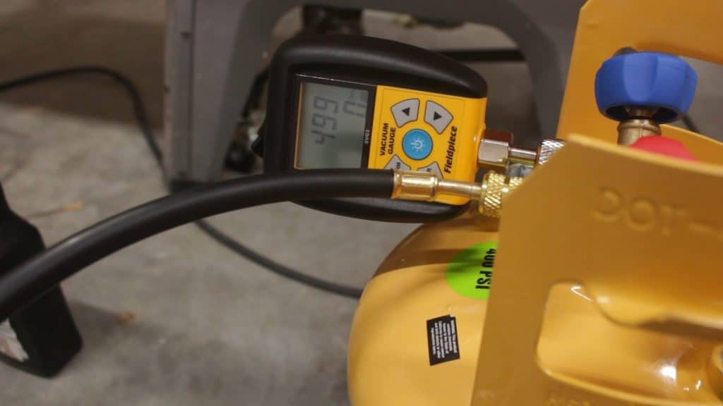
I recorded the weight and subtracted the 1.5kg charge the system required to determine my target weight. When the tank and hose got down to the target weight I knew the system was fully charged. Working with the tank inverted was a bit awkward, but I slowly opened the valve on the bottom of the tank. I then opened yellow port on the manifold. I could see liquid refrigerant flowing into the system through the sight glass on the manifold. I carefully managed the position of the valves on the tank and manifold and frequently checked the system to ensure that I did not overcharge the system. When the tank got close to the target weight, the refrigerant transfer slowed way down. I used a heat gun to apply a gentle heat to the R410a cylinder. Using this technique, I hit the target weight spot on and closed off the valve on the R410a cylinder but left the yellow port on the manifold open.
![]()
I used the heat gun to gently warm the yellow hose and manifold to ensure no liquid was left in those parts of the system. I then closed off the blue port, isolating the system from the manifold. With the system fully charged with the specified weight of uncontaminated R410a, I turned the system on for the first time and took a moment to enjoy the cool air blowing out of the indoor unit. When the system is operating, the gauge pressure drops. Any remaining liquid in the blue line vaporizes because liquid refrigerant at ambient temperature will have a vapor pressure higher than the pressure in the low side of the system during operation. This creates a great opportunity to disconnect blue hose and adapter from the system.
At this point, I was happy to have the most important aspects working. I finalized the last remaining details before arranging with the county building official to inspect the installation. One of those items was building a raceway around the electrical cables and lineset. Another item was 3D printing a hood to install around the penetration where the lineset and drain line left the building.
Cost Details
Performance Observations
I will update this section periodically over time to indicate how the system is performing. I also intend to install a home automation system that will allow me to monitor energy usage. Data forth coming…
Since I installed the unit, in afternoon high temperatures at 95F I have reliably been able to keep the temperature at a comfortable 72-75F. I have measured 65F in the shop with an outdoor high temperature of 85F.
A high efficiency inverter unit like the one I installed works by throttling the system instead of turning it off completely. It seems counterintuitive that the unit runs continuously, but this is how the system is supposed to work. It still seems weird to me since I grew up with low efficiency HVACs that cycle on every 20 minutes. I guess it takes a while to acclimate.
The indoor temperature is about 1-2 degrees above the setpoint displayed on the unit as measured by my Harbor Freight IR thermometer. Not sure if this means the calibration is off on my IR thermometer or maybe the mini split ac controller keeps it just shy of the setpoint. If it is the unit, it makes some sense that the inverter would stay just shy of the set point since the air conditioner mode only pushes the temperature down. If it overshot the temperature setpoint, it would have to switch off–losing the advantage of an inverter based system.
I recently discovered the turn-on-timer and turn-off-timer. I do not work in the shop everyday since video editing and computer work is a fair portion of what I do. I turn off the unit when I will not be working to save energy. I like the turn-on-timer because I can be sure the temperature is right when I arrive in the shop. I then set the turn-off-timer so the unit turns off when I am gone for the day.
All in all. I am really glad I tackled this project. It ended up costing more that it would have if I didn’t have the screw up with the Schrader valve depressor. Regardless, I now have the experience and tools for recovering refrigerant. I have a cool shop and even with all the tools and materials, I came out cheaper than hiring a professional. In my next house, I can install one over a weekend for around $1250 permits and all. I hope this article helps you decide if a DIY approach is for you. If you decide to DIY, be sure to document your installation using a checklist. That data may be valuable if you ever need to contact the manufacturer of your unit regarding its performance.